
In the bitbucket descriptions of the Whisper-Avr I see that the vbatt connector takes a Picoblade, but with batteries only within 0.9 to 3.3 V.. I have a bunch of 3.7 li-poly batteries with JST-PH connectors. What is the best method for using these? I was thinking of making an adapter that attached the battery to the USB connector. IS there a better way?
- Talk21885
Hi todds,
Thanks for the question, I'll try to provide a more comprehensive reply so it might cover related doubts about Li-po batteries and Whisper Node.
Before answering this question it's important to note the following voltage limitations of individual components, as well a few of the Li-po battery details:
MCU: 1.8V to 5V (lower voltages requires slower running speed)
4MBit SPI Flash: 2.3V to 3.6V
RFM69 Radio: 1.8V to 3.6V
Li-po Battery Cell
Fully Charged: 4.2V
Minimum safe voltage: 3V
Self-discharge rate: 5% per month
Li-po Discharge Curve:
![]()
Looking the info above, we can easily say that the Li-po battery is not the best choice for low-power/long-lasting applications, mostly because it has some significant self-discharge rate of 5% per month. In a parallel an Alkaline battery has 2-3% self-discharge per year only.
Also the fact that the Li-po battery voltage goes above and under 3.3V during its full discharge cycle, creates a little challenge to regulate it. But it's not all bad, for applications with constant current draw, specially high currents, those batteries offer great energy density.
Next some DOs and DONT's about how to power Whisper Node with a Li-po Battery:
Li-po @ VBAT: BAD
Powering Whisper Node using a Li-po battery via the Pico Blade connector or VBAT pin is a NO-NO. That's because the step-up regulator will not lower the voltage (buck). This will very likely cause damage to the SPI Flash and RFM69 Radio they will be powered by up to 4.2V.
Li-po @ 3V3_R1: BAD
There's a similar situation if you try to connect the Li-po directly to the 3V3_R1 rail. This will make the rail run at 4.2V when the battery is fully charged, damaging the 3.3V components.
Li-po @ VIN: OK
As you mentioned, connecting the Li-po battery to the VIN, via the Micro-USB or the VIN pin, is the correct approach. Using the VIN pin should be easier than an Micro-USB adapter. You should even find a compatible connector to solder directly into the board using the standard 2.54mm spacing.
Now depending on the current draw from the application, you might not be able to use all capacity available in the battery. That's because you need to consider the voltage drop caused by the Diode and LDO in series. Here two cases:
For a low drain applications, let's say 30mA, you should be OK supplying as low a 3.4V into VIN, which will correspond almost to the end of the Li-po battery charge - around 90% looking at the 0.2C discharge profile above.
Now for higher loads, for example, 200mA, the Diode and LDO voltage drops will be more significant and you might need to supply 3.6V/3.7V into VIN to get a stable 3.3V to the board. From the same chart above, this will represent about 60% of the cell's capacity before the Whisper Node board voltage starts to drop below 3.3V.
Remember that's OK to run things under 3.3V... let's say, down to 2.5V. Just bear in mind that it would be safer/necessary to also reduce the MCU speed and stay close to the specified limits. In this case, running the MCU at 8MHz should be OK:
![]()
Note: The MCU speed can be reduced by changing the AVR Fuses or directly into the code, for example:
Remember that you can easily keep monitoring the VIN voltage and only reduce the MCU frequency when the supply voltage drops below a define threshold.
Buck/Boost External Regulator
Another option would be to externally regulate the Li-po by using a Buck/Boost regulator like this one: https://www.pololu.com/product/2122. This kind of regulator is capable of stepping up or down the voltage, constantly supplying 3.3V. In this case is safe to connect the 3.3V output directly to the 3V3_R1 and bypass the Whisper Node regulators.
Hopefully the information above will clarify a bit about powering Whisper Node with a Li-po battery. I'll try to put together some real-life examples/videos on this subject at some point and add the link here.
Cheers,
Mike M.
Thanks for the question, I'll try to provide a more comprehensive reply so it might cover related doubts about Li-po batteries and Whisper Node.
Before answering this question it's important to note the following voltage limitations of individual components, as well a few of the Li-po battery details:
MCU: 1.8V to 5V (lower voltages requires slower running speed)
4MBit SPI Flash: 2.3V to 3.6V
RFM69 Radio: 1.8V to 3.6V
Li-po Battery Cell
Fully Charged: 4.2V
Minimum safe voltage: 3V
Self-discharge rate: 5% per month
Li-po Discharge Curve:

Looking the info above, we can easily say that the Li-po battery is not the best choice for low-power/long-lasting applications, mostly because it has some significant self-discharge rate of 5% per month. In a parallel an Alkaline battery has 2-3% self-discharge per year only.
Also the fact that the Li-po battery voltage goes above and under 3.3V during its full discharge cycle, creates a little challenge to regulate it. But it's not all bad, for applications with constant current draw, specially high currents, those batteries offer great energy density.
Next some DOs and DONT's about how to power Whisper Node with a Li-po Battery:
Li-po @ VBAT: BAD
Powering Whisper Node using a Li-po battery via the Pico Blade connector or VBAT pin is a NO-NO. That's because the step-up regulator will not lower the voltage (buck). This will very likely cause damage to the SPI Flash and RFM69 Radio they will be powered by up to 4.2V.
Li-po @ 3V3_R1: BAD
There's a similar situation if you try to connect the Li-po directly to the 3V3_R1 rail. This will make the rail run at 4.2V when the battery is fully charged, damaging the 3.3V components.
Li-po @ VIN: OK
As you mentioned, connecting the Li-po battery to the VIN, via the Micro-USB or the VIN pin, is the correct approach. Using the VIN pin should be easier than an Micro-USB adapter. You should even find a compatible connector to solder directly into the board using the standard 2.54mm spacing.
Now depending on the current draw from the application, you might not be able to use all capacity available in the battery. That's because you need to consider the voltage drop caused by the Diode and LDO in series. Here two cases:
For a low drain applications, let's say 30mA, you should be OK supplying as low a 3.4V into VIN, which will correspond almost to the end of the Li-po battery charge - around 90% looking at the 0.2C discharge profile above.
Now for higher loads, for example, 200mA, the Diode and LDO voltage drops will be more significant and you might need to supply 3.6V/3.7V into VIN to get a stable 3.3V to the board. From the same chart above, this will represent about 60% of the cell's capacity before the Whisper Node board voltage starts to drop below 3.3V.
Remember that's OK to run things under 3.3V... let's say, down to 2.5V. Just bear in mind that it would be safer/necessary to also reduce the MCU speed and stay close to the specified limits. In this case, running the MCU at 8MHz should be OK:
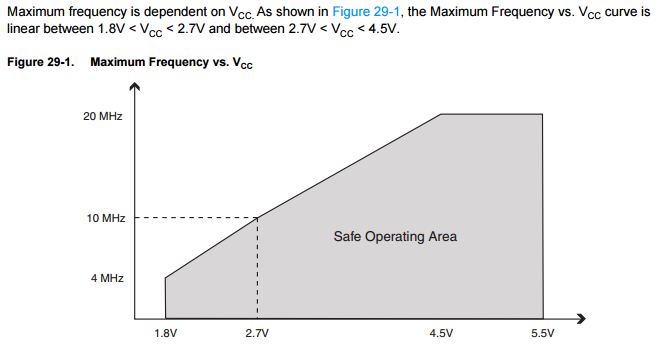
Note: The MCU speed can be reduced by changing the AVR Fuses or directly into the code, for example:
Code
#include <avr/power.h>

clock_prescale_set(clock_div_2); // This would reduce the default 16MHz per 2, making the MCU run @ 8MHz
Buck/Boost External Regulator
Another option would be to externally regulate the Li-po by using a Buck/Boost regulator like this one: https://www.pololu.com/product/2122. This kind of regulator is capable of stepping up or down the voltage, constantly supplying 3.3V. In this case is safe to connect the 3.3V output directly to the 3V3_R1 and bypass the Whisper Node regulators.
Hopefully the information above will clarify a bit about powering Whisper Node with a Li-po battery. I'll try to put together some real-life examples/videos on this subject at some point and add the link here.
Cheers,
Mike M.
Thanks Mike,
Very detailed response. After reading through this I think I will save my Lipo batteries for another project and stick to the dual AA's. I will report back later how long they last serving to power a simple mailbox alerter.
-Todd
Very detailed response. After reading through this I think I will save my Lipo batteries for another project and stick to the dual AA's. I will report back later how long they last serving to power a simple mailbox alerter.
-Todd
Excellent detail in that reply, a great example of fantastic support of a product.
Can you suggest a way of voltage monitoring either 3.7 or 3.2v lipo cells inside an outdoor solar light (setup to also function as a sensor node) using Whisper Nodes ? As per your detail I would imagine using a pololu to set 3v3 R1 to 3.3v but how would you suggest best to monitor the raw battery voltage ? Could also be interesting to observe solar panel voltage as well.
Can you suggest a way of voltage monitoring either 3.7 or 3.2v lipo cells inside an outdoor solar light (setup to also function as a sensor node) using Whisper Nodes ? As per your detail I would imagine using a pololu to set 3v3 R1 to 3.3v but how would you suggest best to monitor the raw battery voltage ? Could also be interesting to observe solar panel voltage as well.
- Talk21885
Hi Johnhi30,
Thanks for the feedback in the first place.
Regarding your outdoor solar light, I understand you wish to use the built-in battery from the solar light to power the Whisper Node, is that correct?
LiFePo4
In first place you have mentioned the 3.7V and 3.2V LiPos. Although both are many times called LiPos, the 3.2V cell battery is actually a LiFePo4 and their voltage range is quite different from a LiPo cell, starting at 3.6V when fully charged, down to 2.5V-2V cut-off voltage.
Now an interesting thing about LiFePo4, as you can see on the chart bellow, is that most of the energy is delivered in an almost "flat curve", between 3.3V and 3V, specially at lower discharge rates.
![]()
If you can confirm that your battery is really a LiFePo4, and the max voltage is 3.6V (including the voltage during recharging), you might be OK to plug it directly into 3V3_R1 rail.
Note that although the SPI Flash and the RFM69 are rated to max. 3.6V, they do have a tolerance before going over the "Absolute Maximum Ratings", which should still be OK if your source of power is slightly above 3.6V (Absolute maximum ratings are 4.6V for the SPI Flash and 3.9V for the RFM69).
LiPo
Now, if your battery is a LiPo, the voltage will vary between 4.2V and 3V, so you could use a Boost/Buck regulator to connect it to the 3V3_R1 or simple connect the battery in the VIN pin and use the built-in LDO.
In my personal opinion, as your cell will be recharged almost every day, it's very likely that the battery will never get close to be fully discharged. So connecting it to VIN will give for free access to the built-in voltage divider, allowing you to measure the battery voltage without any additional circuit.
Voltage Monitor
On the Whisper Node, both VIN and VBat have a built-in resistor voltage divider connected to A6 and A7 pins. You can find all details about it on the link https://bitbucket.org/talk2/whisper-nod ... ge-monitor.
In case you're connecting a power source directly into 3V3_R1, you'll need to build your own voltage divider, but it's a very simple circuit and this site can help you calculating the resistor values: http://www.raltron.com/cust/tools/voltage_divider.asp
Make sure you put 1.1V as Output Voltage and start choosing a big value for the R Top (R1), at least 220K. The reason for 1.1V is that you can use the Internal MCU 1.1V Reference Voltage. Now the reason for a high value R1 resistor is that some current will be always leaking though the voltage divider to ground, even when you're not performing readings - that's the reason why the built-in voltage divider on VBAT has an additional N+P Mosfet circuit to interrupt this current flow when not in use.
Same thing for the Solar Panel, set the Output voltage to 1.1V on the calculator (link above), set the R1 to some high value, maybe 470K and start changing the R2 until you get the Input voltage a bit over the maximum voltage you need to read. If the voltage is too high, like 100V, you'll lost precision, if the input voltage is too close that what you're intending to read, you might go over.
Finally, I also recommend adding a small capacitor (22pF to 10nF) connecting the voltage divider output to ground, this will help stabilizing the circuit, reducing fluctuation during the Analog Read operation.
Example
Assumption: The solar panel will output up to 12V at full sunlight.
Output Voltage: 1.1V
R1: 470K
R2: 33K
Input Voltage (Calculated): 16.767V
Max Current Leak (Calculated): 0.023mA (or 23uA)
To calculate the Leak Current I did:
12V / (470000 + 33000) = 0.000023A * 1000 = 0.23mA
If you're using the Talk2 Library on the Arduino IDE, just try the following code to read the Voltage on pin A1:
ps.: I haven't tried the code, pls let me know if it doesn't work.
Hopefully I was able to clarify your question, cheers!
Mike M.
Thanks for the feedback in the first place.
Regarding your outdoor solar light, I understand you wish to use the built-in battery from the solar light to power the Whisper Node, is that correct?
LiFePo4
In first place you have mentioned the 3.7V and 3.2V LiPos. Although both are many times called LiPos, the 3.2V cell battery is actually a LiFePo4 and their voltage range is quite different from a LiPo cell, starting at 3.6V when fully charged, down to 2.5V-2V cut-off voltage.
Now an interesting thing about LiFePo4, as you can see on the chart bellow, is that most of the energy is delivered in an almost "flat curve", between 3.3V and 3V, specially at lower discharge rates.
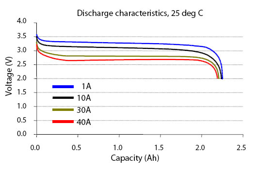
If you can confirm that your battery is really a LiFePo4, and the max voltage is 3.6V (including the voltage during recharging), you might be OK to plug it directly into 3V3_R1 rail.
Note that although the SPI Flash and the RFM69 are rated to max. 3.6V, they do have a tolerance before going over the "Absolute Maximum Ratings", which should still be OK if your source of power is slightly above 3.6V (Absolute maximum ratings are 4.6V for the SPI Flash and 3.9V for the RFM69).
LiPo
Now, if your battery is a LiPo, the voltage will vary between 4.2V and 3V, so you could use a Boost/Buck regulator to connect it to the 3V3_R1 or simple connect the battery in the VIN pin and use the built-in LDO.
In my personal opinion, as your cell will be recharged almost every day, it's very likely that the battery will never get close to be fully discharged. So connecting it to VIN will give for free access to the built-in voltage divider, allowing you to measure the battery voltage without any additional circuit.
Voltage Monitor
On the Whisper Node, both VIN and VBat have a built-in resistor voltage divider connected to A6 and A7 pins. You can find all details about it on the link https://bitbucket.org/talk2/whisper-nod ... ge-monitor.
In case you're connecting a power source directly into 3V3_R1, you'll need to build your own voltage divider, but it's a very simple circuit and this site can help you calculating the resistor values: http://www.raltron.com/cust/tools/voltage_divider.asp
Make sure you put 1.1V as Output Voltage and start choosing a big value for the R Top (R1), at least 220K. The reason for 1.1V is that you can use the Internal MCU 1.1V Reference Voltage. Now the reason for a high value R1 resistor is that some current will be always leaking though the voltage divider to ground, even when you're not performing readings - that's the reason why the built-in voltage divider on VBAT has an additional N+P Mosfet circuit to interrupt this current flow when not in use.
Same thing for the Solar Panel, set the Output voltage to 1.1V on the calculator (link above), set the R1 to some high value, maybe 470K and start changing the R2 until you get the Input voltage a bit over the maximum voltage you need to read. If the voltage is too high, like 100V, you'll lost precision, if the input voltage is too close that what you're intending to read, you might go over.
Finally, I also recommend adding a small capacitor (22pF to 10nF) connecting the voltage divider output to ground, this will help stabilizing the circuit, reducing fluctuation during the Analog Read operation.
Example
Assumption: The solar panel will output up to 12V at full sunlight.
Output Voltage: 1.1V
R1: 470K
R2: 33K
Input Voltage (Calculated): 16.767V
Max Current Leak (Calculated): 0.023mA (or 23uA)
To calculate the Leak Current I did:
12V / (470000 + 33000) = 0.000023A * 1000 = 0.23mA
If you're using the Talk2 Library on the Arduino IDE, just try the following code to read the Voltage on pin A1:
Code
#include <T2WhisperNode.h>

#define VSOLAR_VOLTAGE_PIN A1
#define VSOLAR_MAX_MILLIVOLTS 16767
#define VSOLAR_NUM_SAMPLES 10

setup()
{
  Serial.begin(115200);
  Serial.print(F("Initializing..."));
}

loop()
{

  vsolar = T2Utils::readVoltage(VSOLAR_VOLTAGE_PIN, 0, VSOLAR_MAX_MILLIVOLTS, VSOLAR_NUM_SAMPLES);
  Serial.print(F("Solar Panel Voltage: "));
  Serial.print(vsolar);
  Serial.println(F(" millivolts"));

  delay(1000);
}
Hopefully I was able to clarify your question, cheers!
Mike M.
Great detailed info, thanks Mike. Will be of huge assistance.
I have a selection of housings I was investigating as potential outdoor nodes to report back temp, light levels and motion detection, some of them are LiFePo4 3.2v (IFR14500) others are 3.7v 18650's and one 14500 @3.7v.
The best designed housing so far appears to be the one with 2 x paralleled 2200mah 3.7v 18650's providing 7w of led lighting and recharging with a 5.5v 2w solar panel. Possibly a bit of over kill for a device as lean on power usage as your whisper nodes.
Thanks again for the detail.
I have a selection of housings I was investigating as potential outdoor nodes to report back temp, light levels and motion detection, some of them are LiFePo4 3.2v (IFR14500) others are 3.7v 18650's and one 14500 @3.7v.
The best designed housing so far appears to be the one with 2 x paralleled 2200mah 3.7v 18650's providing 7w of led lighting and recharging with a 5.5v 2w solar panel. Possibly a bit of over kill for a device as lean on power usage as your whisper nodes.
Thanks again for the detail.